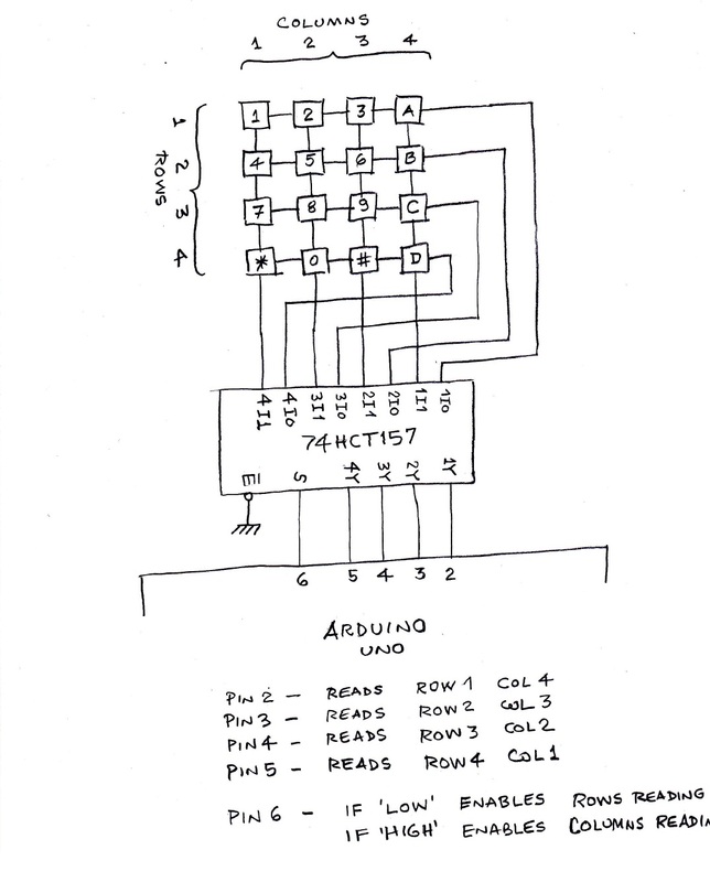
Serial 4 X 4 Keypad Schematic

In this tutorial we are going to interface a 4x4 (16 key) keypad with ATMEGA32A microcontroller. We know that keypad is one of the most important input devices used in electronics projects. Keypad is one of the easiest ways to give commands or instructions to an electronic system. Components Required Hardware: ATMEGA32, power supply (5v), AVR-ISP PROGRAMMER, JHD_162ALCD (16*2LCD), 100uF capacitor, 100nF capacitor, 10KΩ resistor (8 pieces). Software: Atmel studio 6.1 or Atmel studio 6.2, progisp or flash magic.
Circuit Diagram and Working Explanation In circuit PORTB of ATMEGA32 is connected to data port LCD. Here one should remember to disable the JTAG communication in PORTC ot ATMEGA by changing the fuse bytes, if one wants to use the PORTC as a normal communication port.
Keypad input showed to serial monitor with arduino uno and 4x4 keypad full code. Keypad Pin Connects to Arduino Pin. To add the library go to Skeetches -->>Include library-->Type the libray name 'keypad' then press install.Then upload the sketch to your arduino.

In 16x2 LCD there are 16 pins over all if there is a back light, if there is no back light there will be 14 pins. One can power or leave the back light pins. Now in the 14 pins there are 8 data pins (7-14 or D0-D7), 2 power supply pins (1&2 or VSS&VDD or gnd&+5v), 3 rd pin for contrast control (VEE-controls how thick the characters should be shown), and 3 control pins (RS&RW&E).
In the circuit, you can observe that I have only took two control pins, this give the flexibility, the contrast bit and READ/WRITE are not often used so they can be shorted to ground. Compaq Nx9010 Wireless Driver Download there. This puts LCD in highest contrast and read mode. We just need to control ENABLE and RS pins to send characters and data accordingly.